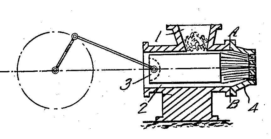
 On the right picture you can see the generalized scheme of the hydraulic and mechanical dry ice making machines, that are produced all over the world.
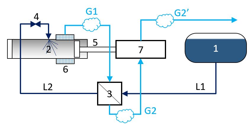
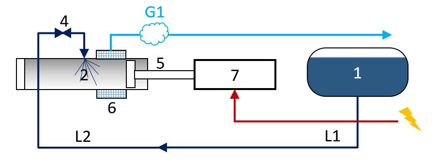
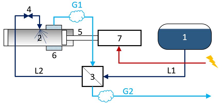
All the machines include pressing chamber 2, pressing plunger 5, forcing drive 5, power engine 7, injection valve 4 and filtration elements 6.
From the tank 1 with the liquid CO2 moves the flow of the liquid CO2 L1, that is infected to the pressing chamber with the atmosphere pressure. During the gas expansion the liquid CO2 transforms to the dry ice snow and a huge amount on the gaseous CO2 that goes through the filters and moves out to the environment or gets pressed, cooled, liquidized again. After the injection cycle the remaining dry ice snow gets pressed with the plunger at the pressure of 160-220 atm, due to the the dry ice snow becomes glassy. Power engine works on the external electric energy source.
On the next step the dry ice gets extruded through the holed matrix that is also needs the huge amount of the energy.
The gaseous CO2 after leaving the pressing chamber has the lower temperature than the temperature of the incoming liquid CO2. In this case the dry ice making machine can be equipped with the heat exchanger in which the liquid CO2 is getting cooled by the gaseous CO2, rising the conversion ratio.