


PU20A - a globally new type of dry ice pelletizerProduce dry ice pellets with maximum economy, reliability and safety
Advantages of PU20A modules
Reducing dry ice losses by eliminating extrusion
Extrusion process video

Image of the principle of pressing a pellet with the energy of compressed air in an » air cushion»
During the extrusion process significant amount of the hydraulic system energy, according to the heat exchanging rule, is converting to the heat energy, while the heat is transferred directly to the dry ice. In PU20A modules every single pellet with the diameter of 20 mm is pressed individually in the «air cushion» (without friction), due to that the dry ice pellet production has no extrusion heat.
On the left video is shown the process of extrusion on the different granulation machines, you can see, how «overheated» dry ice is leaving the extrusion matrix. Ice is being heated when it’s still carried in the pressing chamber under the pressure of 180-200 atm. When leaving the «overheated» ice that got the extrusion heat, begins to evaporate intensively (it goes into an equilibrium state). At the same time in first seconds of pellet leaving the chamber, evaporation occurs from the surface of the pellet, next evaporation occurs due to the ‘overheated’ pellet inner part cooling process.
For the self approximate count of the dry ice losses in the hydraulic granulation machines it is possible to detect time of the pellet extraction from the matrix (from the moment of the leaving starts till the moment of the stop), this time is going to approximately be about 4,0 seconds for the granulator with the productivity of 120 kg/hour and the power of 7.5 kW. It turns that 30 kJ of heat is produced during the extrusion cycle. At the same time granulation machine (120 kg/hour) produces approximately 0.8 kg of dry ice. It is know that the specific heat of evaporation of dry ice is 590,000 J / kg, so we have, that the losses of the dry ice on each cycle is% 30 000 J / [590 000 J/kg x 0.8 kg] = 6.4%, which, accordingly, approximately equal to the loss of dry ice of 7.7 kg/hour for the granulation machine with the productivity of 120 kg/hour.
If we assume that the granulator works for 5 hours a day and 220 days a year, then the loss of dry ice reaches 8.5 tons / year.
More about conversion rate
It is known, that liquid CO2 can not exist under the atmospheric conditions in liquid state. In this case, when it releases the tank it immediately transforms to the CO2 snow and gaseous CO2 in proportion, approximately, 50/50 — that is the base conversion rate. Base conversion rate depends on the pressure of liquid CO2 storage in tank and equal in every part of the world. To accurately determine the base conversion rate, you can always refer to the scientific PH-or TS-diagrams of the state of carbon dioxide.
After obtaining the snow CO2 mass in the pressing chamber, dry ice losses occur as a result of the following integral processes in hydraulic granulators:
— friction on the pressing chamber and matrix while extrusion of the dry ice;
— cooling metal parts of the pressing chamber under the dry ice temperature in to the temperature of dry ice with daily warm start-up;
— heat flow from the hydraulic oil;
— breakdowns of budget versions of hydraulic granulators lead to interruptions in the operation of the equipment.
Reducing the start-up losses of the dry ice due to the reducing metal consumption

Hydraulic granulator pressing unit
When the granulator is started daily, its pressing unit (piston, extrusion matrix, power plates, studs) cools down from the temperature of the environment (+20ºС) to the temperature of dry ice (‒80ºС), meanwhile the pressing unit mass can be 90-180 kg of metall according to it’s productivity and manufacturer. This huge mass of the construction is explains the requirements to the minimal construction deformations when applying a huge pressing force of 30-40 tons. In this case, to cool down this mass to the temperature of dry ice it is needed to evaporate about 7-14 kg of the dry ice on every start-up. If we take the calculation that the granulator is run 220 times a year, the losses of the dry ice reaches 1,5-3 tonnes/year. For comparison in each PU20A module pressing chamber and gate mass contains only 2,6 kg of metal ( 35-70 times less).
Improved reliability

The theoretical fault tolerance of the PU20A modules has been significantly improved by switching to a pneumatic pressing system (hereinafter referred to as PPS) instead of an electrohydraulic pressing system (hereinafter referred to as EHPS).
For fault tolerance calculation has been used average values of components fault tolerance level from the following industrial literature:
- • “Generic component reliability data for research reactor PSA” International Atomic Energy Agency;
- • “Aging and Service Wear of Air-Operated Valves Used in Safety-Related Systems at Nuclear Power Plants” Martin Marietta Energy Systems, Inc.;
- • “Solenoid Valves used in Safety Instrumented Systems” ASCO Valves;
- • “Increased Efficiency of Hydraulic Systems Through Reliability Theory and Monitoring of System Operating Parameters” Jocanović, M. – Šević.
PU20A modules do not have such weak components, due to that the most high-loaded component is the pressing pneumatic cylinder, that works from the 2.5-3 atm compressed air and forming pressing force about 0,7 tonnes in contrast to the EHPS, where this force reaches 30-40 tons.
Below are the statistics on the relative probability of failure of the individual components that make up the four PU20A modules (120 kg / h) and one hydraulic granulator (120 kg / h)
PU20 MODULE (4 pcs )
Hydraulic analogue (1 pc)
Below is a graph of the theoretical fault tolerance level ( % ) of the PU20A modules (4 pieces of 30 kg/hour) and the hydraulic granulator (1 piece of 120 kg / hour), depending on the operating hours of the equipment.
Real level of fault tolerance depends on the price/quality of the components, that are used by hydraulic granulator manufacturer, as well as the level of its maintenance.
As a component base for the PU20A modules, Italian pneumatics from Camozzi and Omal, French electrics from Schneider Electric, Danish valves and liquid CO2 solenoids from Danfoss are used.
It’s important to know that the theoretical source of the pneumatic cylinder according to ISO 19973 is 30 000 km, which is 60 times more than the hydraulic drive (500 km), this is due to the different degree of wear of the dynamic cuffs and guides when rubbing against the sleeve of the hydraulic or pneumatic cylinder.
According to a survey of companies that have purchased low-cost hydraulic granulators, such companies often have to upgrade the hydraulic unit and replace high-load parts (studs, nuts, dies, sleeves) with similar parts made of higher-quality steel.
Compact size

In hydraulic granulators hydraulic unit that generates pressing force is an integral part of the machine. In PU20A module such unit is placed out of the system, that’s why modules became a compact pneumatic electrical machine, which can work from the shop’s compressed air system.
Sizes of one module: 225 mm width, 290 mm depth, 1600 mm height.
Compressed air consumption is 250 nl/min for each module.
Scalability

Due to compact size and ability to hanging PU20A modules on the wall now allows to flexibly scale the production of dry ice in multiples of 30 kg / hour. Modules can be placed close to each other. Width of one module is only 225 mm, what means, that if it’s need the productivity of 120 kg/hour it is need 900 mm of width on the wall, if 240 kg/hour — 1800 mm. At the same time the place on the floor is not used due to the modules hanging.
In hydraulic granulators, everything is the opposite: first, they completely take up space on the floor with their frame, and secondly, it is necessary to leave 1 meter around the frame for its maintenance.
In PU20A modules the whole maintenance can be performed by removing the front panel.
Electrical safe

All electrical components of the PU20A module are powered by an ultra-low safety voltage of 24 VDC (Safety Extra Low Voltage, IEC 60364-4-41:2017), which guarantees maximum electrical safety for personnel.
The power of each module does not exceed 24 watts.
Low noise level

Hydraulic stations, integrated to the hydraulic granulators, has the noise level of 80-90 dB, which creates discomfort and can even affect hearing.
PU20A modules work from the compressed air, that enters from the standard screw compressor with a noise level of about 60-65 dB. Compressor can be placed behind the wall in the other room, in this case maximum level of noise, that PU20A module produces by releasing compressed air through silencers, will be only 60 dB, which is comparable to normal human conversation.
Detailed Information
Technical characteristics of one PU20A module
Main characteristics
- Productivity: 25-30 kg/hour;
- Conversion rate from the liquid CO2 to the pellets: the closest to the theoretical one (no ice heating due to the lack of extrusion);
- Pellet size: diameter Ø20 mm (no extrusion, each pellet is pressed individually ), length 120-160 mm;
- Overall dimensions: 225 mm width, 290 mm depth, 1600 mm height.
Electrical consumption
- Voltage: 24VDC;
- Maximum current: 1 А;
- Average energy consumption: 21 W (0,02 kW);
- Power supply type according to IEC 60364-4-41: 2017
Compressed air requirements
- Average air consumption: 250 l/min;
- Compressed air pressure limits: 2.5 to 3 excess atmospheres;
Liquid CO2 requirements
- Recommended pressure: 14-16 atm;
How PU20A modules work
Step 1. Injection. Under the piston is still working the atmospheric pressure.Due to the spring gas with the pressure 1.0 atm piston is moved up. In the beginning of the cycle injection valve is being open and liquid CO2 is injected to the pressing chamber and transforming to the gaseous CO2 and CO2 snow. Snow is retained in the chamber due to filters and gaseous CO2 mover through the filters to the collector, from where it releases through the top point of the module. At the same time, the CO2 snow has a density of 600-650 kg / m3, it is brittle and crumbly.
Step 2. Pressing. Injection is being stopped and compressed air with the pressure of 2.5-3 atm is supplied to the area under the piston, in turn, the force with a multiplication of 60 times goes to the plunger, that presses CO2 snow and displaces gaseous phase from it’s structure, as a result pellet adopts a solid vitreous structure with a density of approximately 1400-1600 kg / m3 ( https://youtu.be/CxuHx9s0xg0). While pressing pellet starts to press on the inner surface of the pressing chamber, but due to the liquid cover (not shown) around the pressing chamber peripheral part of the pellet is being sublimated and the «air cushion» is formed, as a result friction is reduced to the null and pellet is pressed evenly along it’s length. At the same time the cold of pellet mass, that was evaporated when touching the pressing chamber, passes into the cold of liquid CO2, due to what reduces it’s own temperature. At the same time on the next cycle while injection conversion rate will proportionally be higher due to the transmitted cold. In this way provided inner closed heat exchange process without changing base conversion rate.
Step 3. Releasing and return. The pressure above the piston is being released to the atmosphere and piston fixes in space without force. Gate opens and small amount of compressed air is being supplied over the piston and plunger pushes pellet out of the pressing chamber. Next, re-release the pressure over the piston and spring gas supply under the piston, that makes piston move back to the top point and cycle repeats.
PU20A Module Device
On the right picture is shown the construction of PU20A module. Above the module is placed panel-1, on which the fittings for connecting liquid CO2 are located for suppling liquid CO2, compressed air, exhaust of CO2 gas and 24VDC power supply. Under the panel-1 two pneumatic distributors-2, that manage compressed air flows for moving up pneumatic cylinder -3 piston and pushing on piston for dry ice pressing process. The electrical cabinet-4 includes a smart relay with solid-state outputs with a time delay for each cycle and a fuse. Pressing unit-6 includes stainless pressing chamber, liquid cushion from gaseous CO2 storage collector. On the bottom part on the module stainless steel rotary shutter-6 is placed with anti friction sliding metal rings. Opening and closing of the pressing chamber is carried out by means of a rotary pneumatic actuator-7. On top of the pressing unit-5 is the mechanism-8 injection of liquid CO2 with a solenoid.

Module PU20A pellets quality
Pellets evaporation testing on the open air

Dry ice pellets production system

On the picture you can see the main components of dry ice pellets production system on the base of PU20A modules. This system must contain at least:
- liquid CO2 storage tank with the pressure of 14-16 atm;
- screw compressor with receiver and with a capacity of 250 nl / min per module;
- two compressed air pressure filter regulators (1 and 2.5 atm) for powering the modules;д
- ultra-low safe voltage source 24 VDC with a power of 24W per module;
- liquid CO2 circulation pump between modules and heat-insulated hoses;
- modules
Our offers
PU20A Modules
- Package
- Delivery
- Basic connection diagrams
- Instruction manual
System components
- Pneumatic components, electrical components, strapping for the assembly of the granulation system as a whole
- Package
- Delivery
- Accurate installation drawings (standard turnkey project)
Installation supervision
- Control of the installation on the client's territory
- Excluding relocation
- Excluding accommodation
- Excluding travel expenses
Start-up and commissioning
- From assembly to first start-up
- Excluding relocation
- Excluding accommodation
- Excluding travel expenses
History of technology development
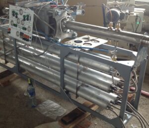
Experimental sample
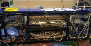
Prototype
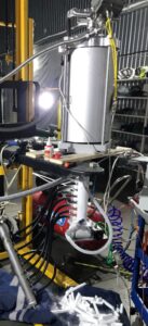
Pre-industrial sample
