What is the conversion factor for the pelletizer?

By in
What is the conversion factor for the pelletizer?

The main function of dry ice production machine is transformating liquid CO2 into the pellets of dry ice. Let’s study this procees more detailed with splitting into stages.  

Storage and feeding liquid CO2 to the granulator

As we know, the liquid CO2 always stored in the tank with exact pressure. Recomended storage pressure of the liquid CO2 for the ontimal dry ice production machine’s work is from 16 to 18 atm. The lower pressure is used in the tank, the lower is the temperature of liquid CO2. Traditionally, the fittings of the liquid CO2 delivery tank are connected to the granulator through strong and flexible hydraulic hoses or through welded steel pipelines. For the more effective dry ice production machine work, it is recommended to fix the collector-separator-filter over it, where the CO2 gases are removed and liquid CO2 is filtered from microscopic solid parts. 

Liquid CO2 throttling

Throttling is the adiabatic expansion of a liquid in an open system under stationary flow conditions without performing external work and increasing the speed on the control surface.
 
Arkharov A. M., «Cryogenic system. Volume 1. Fundamentals of theory and calculation»

In the case of granulators, the control surface is a valve or nozzle for supplying liquid CO2 to the pressing chamber, through which the liquid CO2 loses pressure below the pressure of the triple point of CO2 (5.12 ATM) and thereby turns into a two-phase mixture (in gaseous CO2 and dry ice snow).

The proportion of the mixture (gas: snow) has a constant value for each pressure level (16-18 ATM), regardless of the location of the granulator on the globe. Thus, the basic conversion rate from liquid to snow is always the same for all dry ice production machines.

The figure on the right shows a TS diagram for understanding the pellet production method. Point A1 is located on the saturation line a1-a2 and characterizes the state of carbon dioxide in the liquid aggregate state (L) when stored in a tank at a pressure of 1.8 MPa (selected for example), line A1-A2 shows the process of a sharp drop in the pressure of liquid carbon dioxide (L) from point A1 to point A2, where point A2 shows the thermodynamic equilibrium of a mixture of solid carbon dioxide (S) (point A3) and gaseous carbon dioxide (G) (point A4), based on this, the proportion of solid carbon dioxide obtained is equal to the result of dividing the length of the segment A2-A4 by the length of the segment A3-A4 and is approximately 0.51 (51%).

Your Diagram TitleВпрыск жид. СО2 → Газ. СО2 (через фильтр): 50%Впрыск жид. СО2 → Снег СО2 в камере: 50%Впрыск жид. СО2: 100%Впрыск жид. СО2: 100%Газ. СО2 (через фильтр): 50%Газ. СО2 (через фильтр): 50%Снег СО2 в камере: 50%Снег СО2 в камере: 50%

Filtration of a two-phase mixture

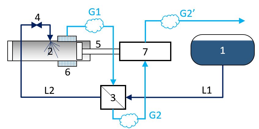
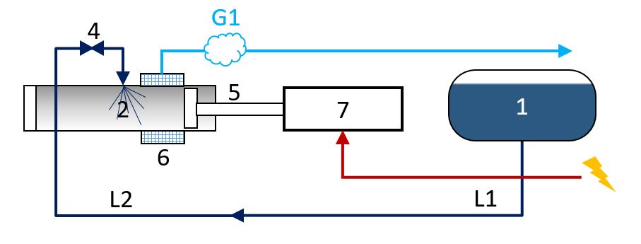
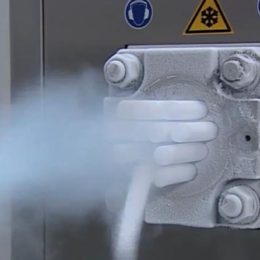
When liquid CO2 is injected into the pressing chamber, liquid CO2 is partially converted (for example, by 50%, taken for simple perception) into gaseous CO2 and by 50% into dry ice snow.

Technical information:

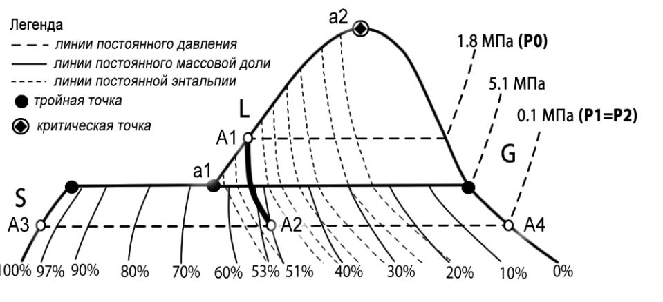
  •  The density of liquid CO2 at 16 ATM: 1060 kg/m3;
  • Density of cold CO2 gas at 1 ATM: 2.5 kg / m3;
  • Dry ice particle density: 1600 kg / m3 (approx.);

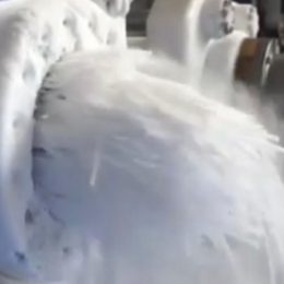
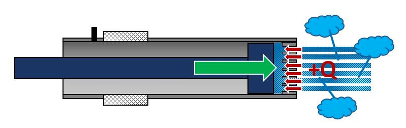
Half of the liquid CO2 stream turns into gaseous CO2, which is accompanied by a 424-fold increase in the volume of this half of the stream (1060/2,5). As a result, a complex vortex flow of a two-phase mixture forms in the pressing chamber. The task of the filter is to keep the dry ice snow in the pressing chamber as much as possible.
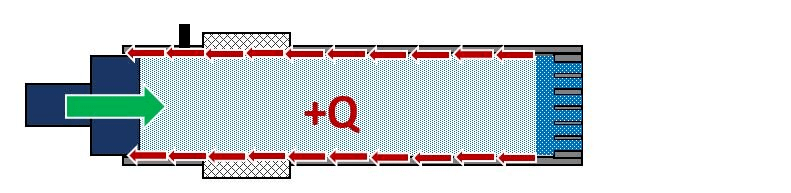
The sources of waste

The heat from the extrusion

During the extrucion procces, the surfaces of matrix and chambers contacted with extruded material, are subjected to significant local heating.

The processes of evaporation of granules when they are released into atmospheric conditions are presented below. Since ice is pressed under high pressure, the heat that it received from friction does not immediately pass into steam, but is kept under pressure in the chamber. After exiting, the pressure around the ice becomes atmospheric and evaporation occurs.

Heat from the hydraulic system

Heat flow from hydraulic oil through the pressing piston, studs, frame, and convection inside the frame shell. Hydraulic cylinder working temperature is usually about + 80, it can reach +100 °C in extreme conditions. It occurs due to the losses, when the part of electrical energy (10-15%) in the hydraulic drive converts to heat. Part of this heat brings out with the cooling system, but some goes to the pressing chamber.

Compaction friction

On this site the snow of the dry ice is being compacted and it's friction on the pressing chamber is insignificantly.

Pulp pressing friction

Glassy shape compacted snow under the pressure of 160-220 ATM becomes viscous and begins to press on the side walls of the pressing chamber. This friction is one of the highest during the dry ice production cycle.

Calculation example

For example, to calculate the losses of hydraulic granulator operation with productivity G=120 kg/h and power N=10 kW, you need to take an efficiency factor of 87% (approximately), to get the power (8,7 kW) on the plunger in the pressing chamber. 

For example, base conversion coefficient is 2.0, which means that the relation of the solid and the gaseous phase is 50/50, so you need 2 kg of liquid to produce 1 kg of the snow.Measure the time of the extrusion from the moment of increase in noise to the moment of pellets exiting from the matrix, and the whole process time. For the traditional machines this values are approximately 6 and 24 seconds, which means 25% of the whole machine’s working time (we should also add about 5% for the snow pressing process ) – this is the plunger working time, when the whole hydraulic system power goes on the overcoming friction in the pressing chamber and matrix holes. Friction heat: 

Q=N • 87% • 30% = 2,6 kW.

Let’s take the efficiency of the heat bringing out from the hydraulic system as 50%. Heat flow from the hydraulic system to the pressing chamber:  

Q=N • (100% — 87%) • 50% = 0,6 kW.

The total heat flow to the dry ice in the process of it’s production is Q= 3,2 kW. 

Because the scecific heat of dry ice sublimation is about k= 590 000 J/kg, the dry ice loss will be about:  

G = Q / k= 0,0054 kg/s = 19,5 kg/hour

Let’s calculate the actual flow rate to the liquid: 

G(liquid) = (G1+G2 )/0,5=279 kg/hour 

Final conversion rate subject to the total efficiency and actual liquid flow rate:    

x= G(liquid)/G(granulator)=279 / 120 = 2,3

In this way, using such a hydraulic granulator during one year (2000 working hours) customer loses dry ice by weight:    

G(potential) • 2000 hours = 19,5 kg/hour *2000 hours= 39 000 kg

and consumes electricity in the amount of:  

N • 2000 hours = 20 000 kW/h

Improvement Methods

Friction on the matrix and from internal deformation of the pulp into pellets

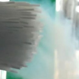
When the ice passes through the matrix, there appears one more force,
needed to overcome the deformation resistance. At the exit "overheated" ice begins to evaporate immediately until it reaches the equilibrium state.

Liquid heating with exhaust gas


Here are the main physical parameters of substances: 


Liquid CO2 at 16 ATM:

  • Temperature before the heat exchanger  [Tl]: -26 С;
  • Temperature after the heat exchanger [Tк]: unknown;
  • Heat capacity  [Cl]: 2100 J/kg*sec;

СО2 gas at 1 ATM:

  • Temperature after the pressing chamber (before the heat exchanger) [Tг]: -78 С;
  • Temperature after the heat exchanger [Tк]: unknown;
  • Heat capacity [Сг]: 778 J/kg*sec;

Dry ice at 1 ATM:

  •  Temperature: -78 С;
  • Specific sublimation heat [k]: 590 000 J/kg;
  • Looking at the above temperature values it is logical to solve this problem by installing the coil, the task of which will be to transfer the cold of outgoing flow of the gaseous CO2 to the liquid CO2. This can increase the snow yield at the next injection of cooled liquid CO2. Let’s assume, that heat-exchange is performed at 100%, which means that the liquid C02 is cooled to the temperature Tk, and the gaseous CO2 is being heated to the temperature Tk. Let’s also take the mass flow of the liquid CO2 as a unit (1), but the conversion factor is 50/50, so the mass flow of the gaseous CO2 is going to be 0,5 units. 

Let’s make the equation for the conservation of thermal energy: 

(Тк-Тж)•Сж•1+(Тк-Тг)•Сг•0,5=0

Let’s use numbers without specifying units of measurement, because all values are in the SI system: 


(Тк+26)•2100•1+(Тк+78)•778•0,5=0

Тк•2100+54 600+Тк•389+30342=0

Тк•2489+84942=0

Тк=-34,1 С

Now we calculate the cooling power, that is given to the liquid CO2 in the heat exchanger for the pellets production capacity at 100 kg/hour ( consumption of the liquid CO2 will be 200 kg/hour = 0,0556 kg/sec). 


N=(-34,1[С] +26 [С]) • 0,0556 [kg/sec] • 2100 [J/kg*sec] = 934 W,

that is in general not high cooling power, household air conditioner cooling power is even higher.  

Let’s calculate the additional yield of pellets. The simplest way is to imagine that the whole amount of the cold is used for pellet production from the gaseous CO2 (desublimation).  

G= 934 [W] / 590 000 [J/kg] = 934 [J/sec] / 590 000 [J/kg] = 0,00158 [kg/sec] = 5,7 kg/hour

In this way, the heat exchanger theoretically allows dry ice production machine with the capacity at 100 kg/hour to produce additional 5,7 kg/hour of pellets.

About PU20 module

There is no pressing friction

Due to the innovative design every pellet is being pressed almost without the friction and at the same time individually, that allows to reduce costs on liquid CO2.

Integrated heat exchanger

Innovative heat exchanging device is provided in modules, that allows to reduce costs on liquid CO2 due to high intensification.

Energy-independent pressing system

The modules have an innovative dry ice pellets pressing system, that needs only 14 W.

Dry ice production machine's diagram

  • 1 — liquid СО2 storage;
  • 2 — pressing chamber;
  • 3 — heat exchanger;
  • 4 — liquid CO2 injection valve;
  • 5 — pressing plunger;
  • 6 — filtration system;
  • 7 — pneumatic drive, working on gaseous CO2; 
  • G1 — working CO2 gas;
  • G2 — working CO2 gas after the heat exchanger;
  • G2` — working CO2 gas after working off.