Рубрика: Chemicals

Benefit calculator for PU20 modules
Using this calculator, you will be able to evaluate the potential benefits of using advanced granulation modules produced by IRBISTECH in comparison with the use of hydraulic granulators.
Assumptions: loading of the granulator is 8 hours every working day; the owner of the production does not repair the granulator himself.
One & Transformer (EN)
Transformer - globally new dry ice blaster Use up 20 mm pellets for power and economical cleaning

Model "One" only for small pellets (1.6 and 3 mm)
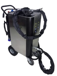

Cleaning with only 3 mm pellets
Without the possibility of changing the size of the granules (degree of aggressiveness/softness of cleaning)

Air consumption from 3500 l / min
With lower compressor performance, the cleaning efficiency decreases

Super sonic nozzles
Reduction of dry ice consumption due to maximum air acceleration in nozzles with a special profile
Model "TRANSFORMER" with internal grinder (3-20 mm pellets)


Use any pellets
Increasing the storage time and extending the cleaning period

Cutting of pellets into particles with determined size
Reduction of dry ice consumption due to faster acceleration of small particles. Choosing of size od pearticles 1, 1.5, 2, 2.5, 3 mm

Air consumption 800 L/min and more
With small particles, you can use nozzles with a smaller wire cross-section, which save compressed air.

Super sonic nozzles
Reduction of dry ice consumption due to maximum air acceleration in nozzles with a special profile
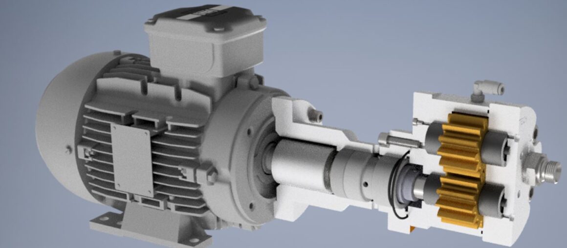
The revolutionary grinder in Transformer

Why to grind large pellets?
Historically, 1-1.6 mm pellets have been used for dry ice cleaning, but since they evaporated too quickly, users switched to 3 mm granules, sacrificing cleaning efficiency. Advantages of fine particles of solid dry ice:
- The finer the particles, the more they are accelerated in the nozzle and better clean;
- The finer the particles, the denser the cleaning jet (particles are better distributed over the cleaning spot).
For example, 16 mm pellets have up to 5 times less specific surface area to weight, due to which they evaporate more slowly, which in turn gives the following advantages:
- The loss of pellets during transportation is reduced;
- The loss of pellets during storage is reduced;
- The loss of pellets during the usage is reduced.
Also, the gentle technology of cutting granules from IRBISTECH provides the following advantages:
- Any dry ice pellets can be used;
- The pellets are almost equal in size;
- You can independently choose the target size of the particles range: 0.3-0.7, 1-2 and 2-3 mm.
Comparison of granule grinding technologies
Shearing
You can use:
- 3 mm rize pellets
- 6-16 mm pellets
Shearing-the body is divided into parts of predetermined sizes and shapes. The process is fully controlled.*
This grinding technology is used in the dry ice cleaning machine model «TRANSFORMER«.

Shaving
You can use:
- 3 mm rize pellets
- 6-16 mm pellets
- Slice and bricks
Shaving -the blades scrape a thin layer from the body of the pellet, resulting in the formation of small particles resembling flakes and dust.
Compressing
You can use:
- 3 mm rize pellets
Compressing – the body under the action of load is deformed throughout the volume and, when the internal stress exceeds the compressive strength, is destroyed. As a result of this destruction, particles of various sizes and shapes are obtained.
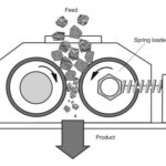
* Technological publication » Grinding in the chemical industry”, Sidenko P. M., Publisher: Chemistry, Year: 1977
Supersonic nozzles for the ONE and Transformer
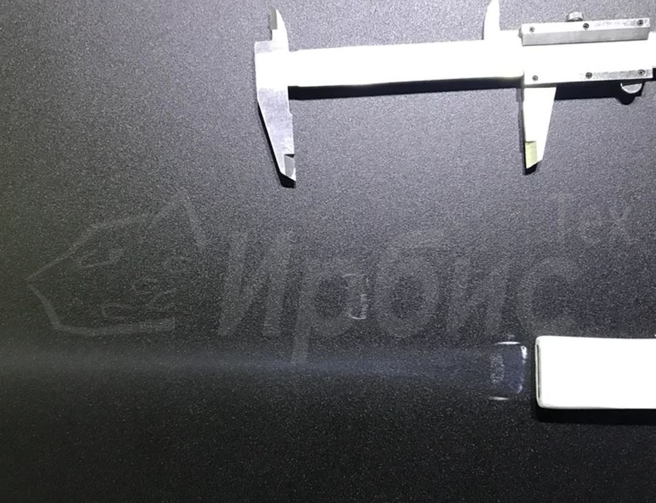
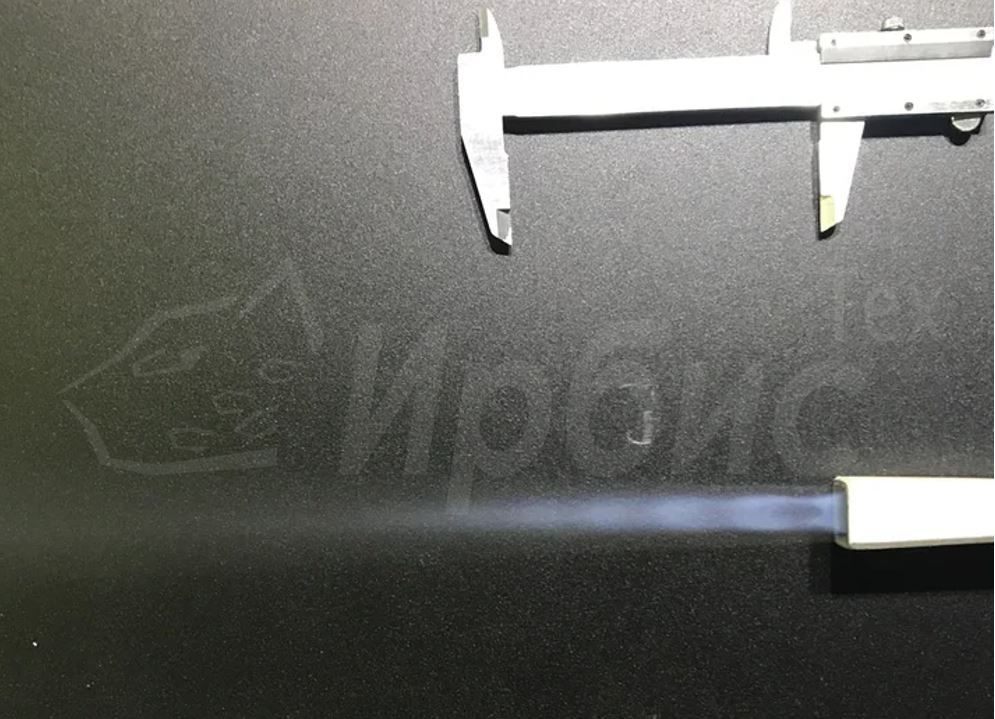
Dry ice super sonic nozzle
What distinguishes the IRBISTECH nozzles?)

We have been continuously optimizing our nozzles since 2016.
It is known that the specific consumption of pellets for cleaning 1 square meter of dirt depends on:
- Source compressed air pressure
- Compressed air consumption of the source
- Dry ice cleaning machine throughput
But not a lot of customers pay attention to such parameters as:
- Nozzle length (affects how long the pellet can accelerate)
- Nozzle length (affects how long the pellet can accelerate) Speed distribution in the nozzle (affects how fast the pellet can accelerate)

Long supersonic nozzles from IRBIT are able to keep the supersonic flow along the entire length of the long nozzle, due to which the pellets acquire a higher speed. In flat nozzles, when their length increases, the supersonic flow is disrupted due to boundary layers.
Schematic diagram of the Transformer

Features

Designed in accordance with the:
- IEC 60204-1 Safety of machinery;
- IEC 60364-4-41:2005 Protection against electric shock.

Designed in accordance with the:
- ISO 12100:2010 «Safety of machinery — General principles for design — Risk assessment and risk reduction.

Electrical cables are used according to the VDE standard

Easy-to-use operator panel

PLC-free automation

Flexible pneumatic wheels

Kit for both blasters
Lightweight and flexible jet hose (4.5 mm)

Functional operator handle (24VDC)

Case

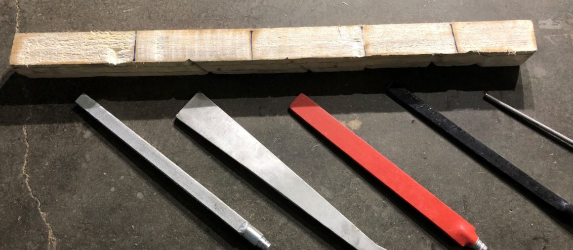
Mini nozzles (500-2000 L/min)

Flat universal nozzle (3500 OR 5000 l/min)

Individual long supersonic nozzle (3500 OR 5000 l/min)

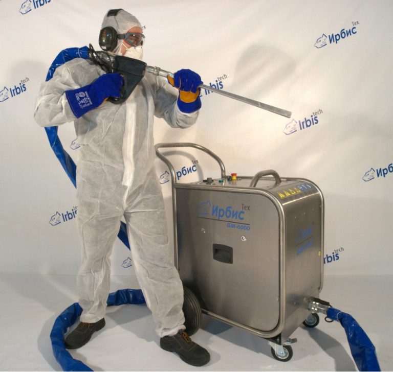
Protective headphones

Protective glasses

Frost-resistant gloves

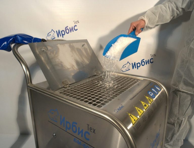
Scoop for ice

Spare parts and accessories
Angular nozzles

Super-wide nozzles

Extension of the electro-cryogenic hose
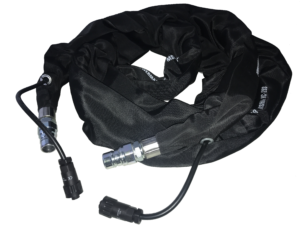
Operator's gun

Aluminum operator's gun

Spare set of seals and portion shaft

Technical Specifications
- Consumed pellets size (TRANSFORMER): 3, 6, 9, 16 mm
- Consumed pellets size (ONE): 3 mm
- Pellet consumption: up to 120 kg/hour
- Cleaning pressure: up to 12 atm
- Air consumption: up to 10 000 liters/min
- 0.55 kW (ONE) и 1.3 (Transformer) at 220VAC (2P+E);
- 115 kg (ONE) и 130 kg (Transformer);
- 963x461x1262 mm

Testimonials
Performed demonstrations

Subsidiary of Rostec

PJSC Tatneft

JSC RusHydro

PJSC GAZ

PJSC Tatenergo

Nestle
Selecting a compressor for cleaning

Removal of dirt of light complexity, which can be almost removed with a rag by hand (for example: oil deposits, light deposits, loose and brittle dirt, industrial dust, street dirt): working pressure 6-7 atm and 3 cubic meters / min according to FAQ
For the removal of medium-sized dirt (including paint, deposits, grease deposits, food soot, dried glue and bitumen): working pressure 8-9 atm and 5-6 cubic meters / min according to FAQ
For the removal of high-complexity contaminants (including old rust,» stone » deposits on the steam turbine, polymer and fire-fighting paint): working pressure of 10-12 ATM and 7-9 cubic meters / min according to FAQ
FAQ (Frequently Asked Questions)
1. What distinguishes pellets from ordinary dry ice, which is used in ice cream makers on the street?
Dry ice granules are obtained by pressing at a pressure of 160-200 atm, due to which its density becomes very high, and the lumen of the granules is almost transparent. Regular blocks of dry ice, white in color and very fragile. granules, in turn, are loose and solid, so they are used for high-quality cleaning.
2. Can the briquettes/blocks be used for cleaning in machine ONE?
No, only small cylindrical pellets with a diameter of 1.6 or 3 mm.
3. Can the briquettes/blocks be used for cleaning in a machine with a grinder?
The grinder in the TRANSFORMER machine can only accept loose pellets with a size of 3 to 20 mm in diameter, it does not work with blocks.
4. Where does dry ice go after cleaning?
It immediately evaporates and turns into CO2 gas.
5. Where does the contamination go after cleaning?
It flies off in the direction where the air jet with pellets blows. dry ice is inert and does not interact with dirt and the surface to be cleaned.
6. Will the dry ice cleaning process affect the breath, because CO2 is released?
When cleaning, a screw compressor is used, which supplies a large amount of air during the cleaning process through the nozzle, so in 99.99% of cases, there are no breathing problems. if the room is closed, has a small volume or low ceilings, and the container with pellets is located in it, then there is a need to ensure constant ventilation of the room. This is explained by the fact that CO2 is heavier than air.
7. Where can I get dry ice?
Dry ice is sold in some large cities of Russia by independent producers, so dry ice is a market commodity, not a monopoly. In order to find out the nearest manufacturer of dry ice, you can contact IRBISTECH, our specialists are always ready to provide this information.
See the article «Organisation of dry ice production«
8. How to store dry ice?
Storage is carried out in special industrial thermal containers on wheels with a capacity of 100,200,300 kg of ice; there are also inexpensive household containers for 50-75 kg with good characteristics, made of foam. All these containers have basic properties: tightness and a wall thickness of 10 cm. Some local dry ice producers provide containers for rent.
9. How quickly does dry ice evaporate in containers?
5-8% of the volume per day. The rate of evaporation depends on the time of year. Before the first opening of the container, 3-millimeter pellets can be safely stored for up to three days without changing their properties. Large pellets with a diameter of 6-20 mm evaporate more slowly than pellets with a diameter of 3 mm, due to the smaller specific area per 1 kg of pellets.
10. What can be break in the machine?
In the machine, everything is thought out so that, with proper operation, it will serve for many years. In case of violation of the operating rules, the following damages may occur:
- breakage of the operator’s handle when it is hit hard;
- damage and abrasion of the batch shaft with a seal, knives and shredder sieves in case of frequent ingress of solid dust into the hopper or through the air flow, as well as in case of a single ingress of a large solid object into the structure, such as, for example, a nut or bolt.
11. What are the requirements for compressed air?
For uninterrupted operation of the plant, the compressed air must have a low humidity (the maximum value is 5% relative humidity, the dew point is below 0°C). The compressed air must be free of oil, dirt and large particles. The compressed air must, at a minimum, comply with the air quality indicators according to «ISO 8573, class 3».
12. Which compressor should be used for cleaning?
Compressor for a point solution: removal of dirt of light complexity, which are easily removed by hand with a rag (for example: oil deposits, light deposits, crumbly and brittle dirt, industrial dust, street dirt): working pressure of 7 ATM and 3 cubic meters / min according to FAD (estimated price 330,000 rubles. with an electric drive of 18 kW);
Universal compressor for cleaning services: for removing medium-complexity dirt (including paint, deposits, grease deposits, food soot, dried glue and bitumen): working pressure 8-9 ATM and 4-5 cubic meters / min according to FAD (estimated price 600,000 rubles. with an electric drive for 30 kW);
Special applications: for removing high-complexity contaminants (including old rust,» stone » deposits on a steam turbine, polymer and fire-fighting paint): working pressure of 10-12 ATM and 7 cubic meters / min according to FAD (estimated price 900,000 rubles with an electric drive of 55 kW).
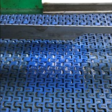
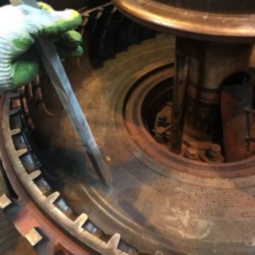
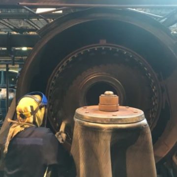
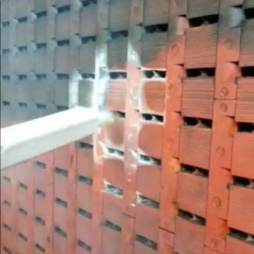
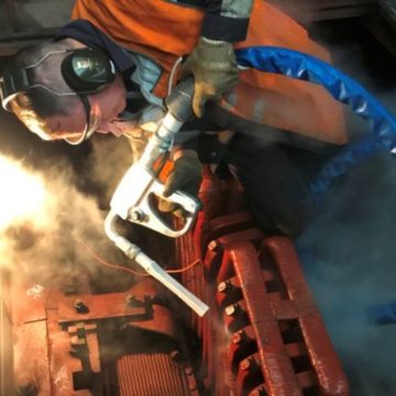
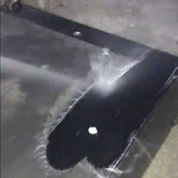
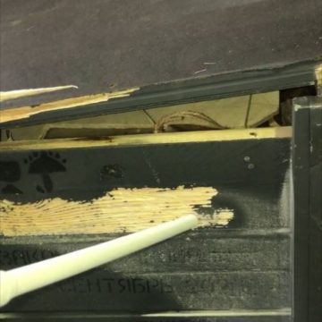
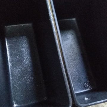
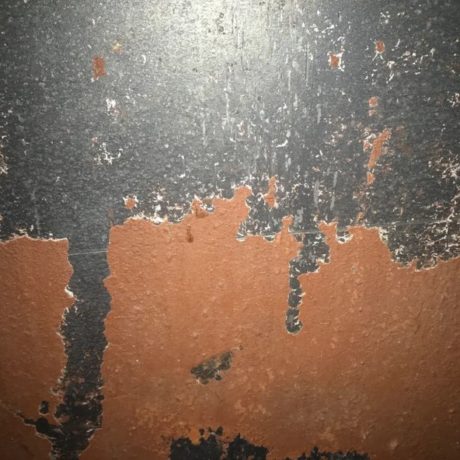
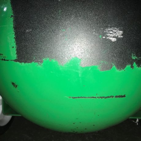
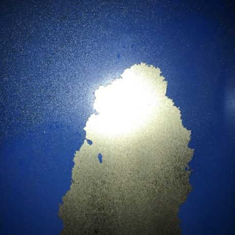
Light contaminations Cleaning examples
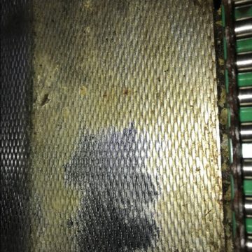
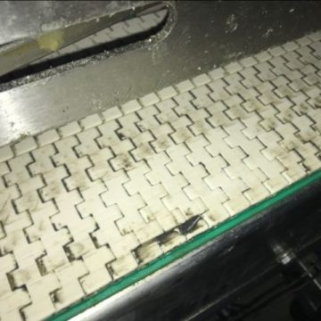
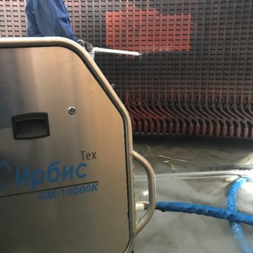
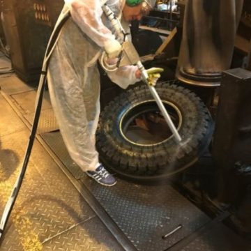
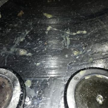
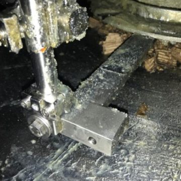

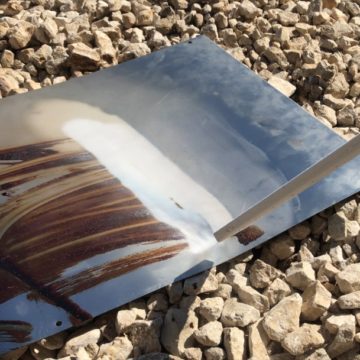
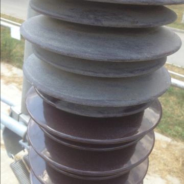
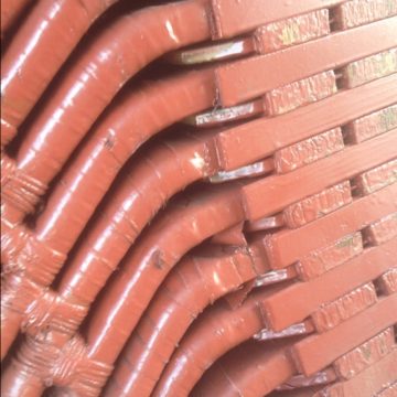
Persistent contaminations Cleaning examples
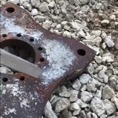

IrbisTech YouTube channel
On our video channel you can find a lot of videos with the cleaning various contaminations
Four year long Development

First sample

First generation

Second generation (Transformer)
Parameters optimisation
While testing the samples the In the process of testing the samples, researches were carried out to optimize the power of engines, the consumption of pellets, the materials of rubbing materials, and the operation of electronic components
Low temperature testings
Components and units of the machine were tested on the long lasting dry ice temperature impact, thus, the study of fault tolerance during long-term operation was carried out.
Resource tests
The rubbing parts were analyzed for the rate of wear, which made it possible to develop a long-lasting dry ice cleaning system
Request for worldwide customers
About company IRBISTECH
The features of the company
We are OEM-manufacturer
«original equipment manufacturer»
ОЕМ-manufacturer is a true manufacturer, such is a company IRBISTECH.
Our intellectual property
One of the main competitive advantages of the IRBISTECH is an intellectual base, build on the special knowledge in the field of the dry ice.

Federal and regional structures support us
In the period of construction and research, company was supported with The Fund of assistance to innovation, The investment and venture Fund of the Republic of Tatarstan, the SKOLKOVO Foundation, and the Ministry of industry and trade of the Russian Federation.


Innovation of the company
In 2016, the company was awarded the status of a resident of the SKOLKOVO Foundation (certificate No. 1121487), which absolutely indicates the fact that IRBISTECH is an innovative company and its technologies has global importance.
The research is supported by a grant from the «SKOLKOVO Foundation»
The process of the high-technology products creating
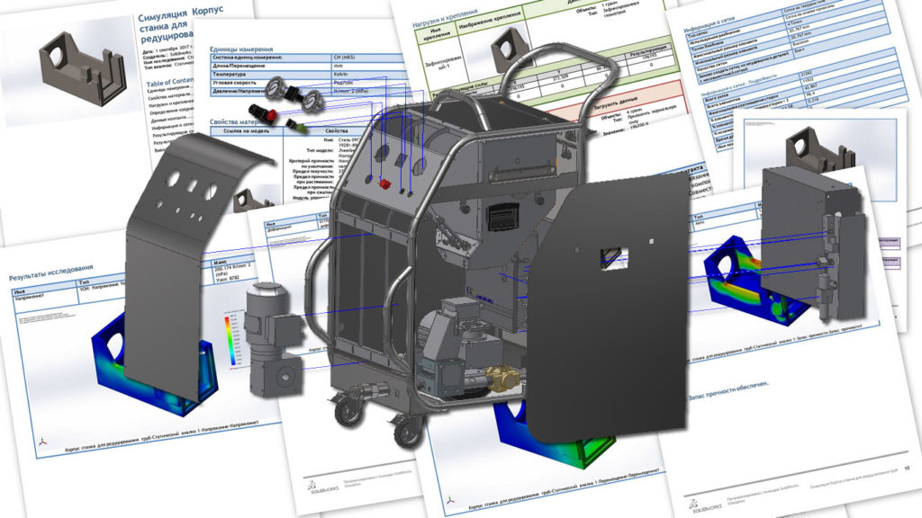
Development in the official CAD system
All the power calculations, gas-dynamic and temperature calculations, 3D design and design documentation are performed in licensed software packages.

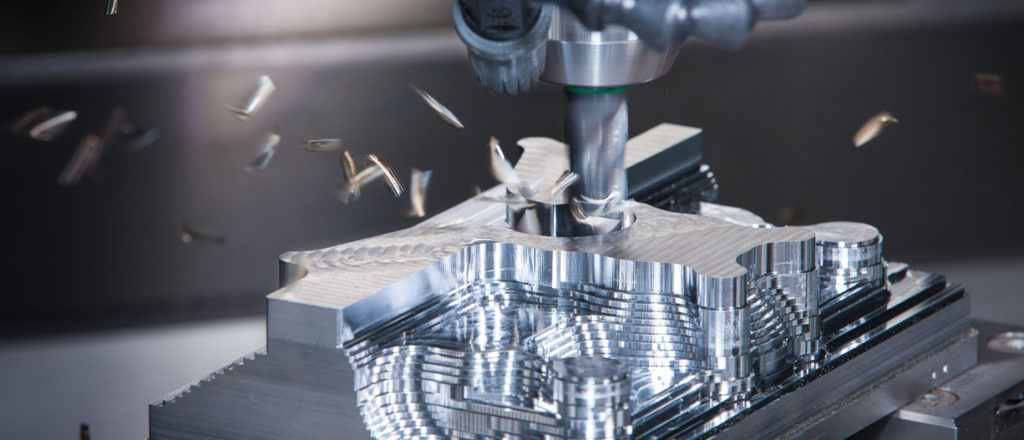
Manufacturing of elements on high-precision CNC-controlled equipment
Production of critical parts that are in constant friction and are responsible for the tightness of the equipment, are made on CNC milling machines with an accuracy of 10 microns.
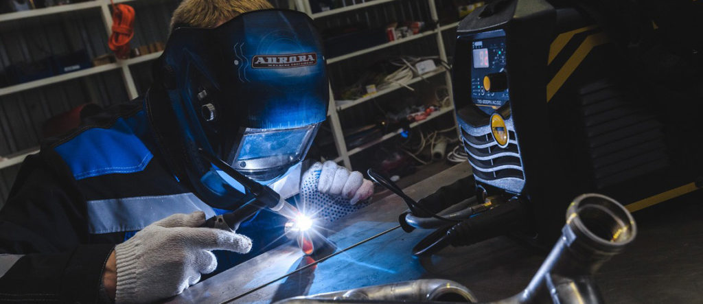
Welding of stainless and aluminum parts
When assembling the equipment we use modern split and all-in-one assembly technologies: TIG-welding of the stainless steel in argon, soldering of stainless steel with silver-plated solders, stainless bolt connections.
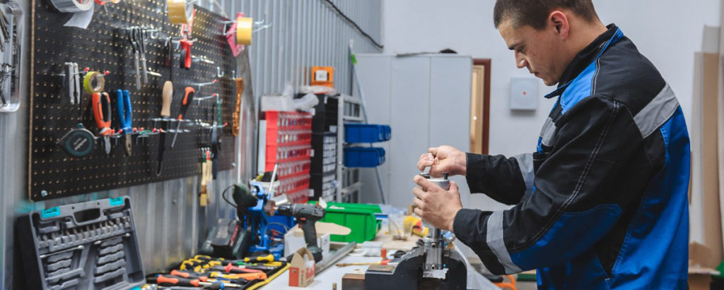
Gentle manual assembly
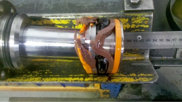
After the final assembly we apply tests on electrical safety, leakproofness and verification of the declared technical characteristics are being conducted.
Disadvantages of hydraulic pelletizers
The main components of the hydraulic granulator

1. Hydraulic pump with a pressure of up to 220 ATM with a powerful electric motor of 5-15 kW; 2. Hydraulic distributors operating at 220 ATM; 3. Hydraulic hoses running at 220 ATM; 4. Tank for hydraulic oil

5. oil filters;

6. Hydraulic cylinder for pressing dry ice, which creates a gain of up to 40 tons;

| 7. Large-diameter compression chamber with binding pins that can break; |

8. A complex system of management and control over the condition of the granulator. The photo of the HMI panel shows a window with an image of possible 21 granulator errors, of which 14 are related to the electro-hydraulic system.
MAIN FAILURES OF HYDRAULIC SYSTEM


№ | Defect | Possible cause |
1 | The pump does not supply liquid to the system | Incorrect direction of rotation of the pump shaft |
There is not enough working fluid in the tank | ||
The suction line is clogged | ||
Air suction in the suction pipe | ||
Pump failure | ||
The viscosity of the liquid is high | ||
The overflow valve damper is clogged | ||
2 | The pump does not generate pressure in the system | The pump does not supply liquid to the system |
High wear of the pump (internal leakage is large) | ||
High external leakage along the shaft through the pump housing | ||
High internal leaks in the hydraulic system | ||
The safety valve spool or overflow valve is jammed and cannot be installed on the seat | ||
Reduced oil viscosity due to heating (usually above 50 C) | ||
3 | Noise and vibration in the system | High resistance in the suction line |
The filter throughput is low or it is clogged | ||
Air suction in the suction pipe | ||
The breather in the tank is clogged | ||
Valve vibration | ||
A sharp change in the flow section of pipelines | ||
Non-rigid fastening of pipelines | ||
4 | Unequal movement of working bodies | Air in the hydraulic system |
The pressure setting of the safety valve is close to the pressure required for the movement of the working units | ||
Low back pressure on the cylinder drain | ||
Mechanical jamming of the moving parts of the hydraulic cylinder. Uneven oil supply by the pump. Noise and knocking in the pump due to failure of one of the blades or plunger | ||
5 | A sharp decrease in speed when the load increases | Large internal or external leaks in hydraulic system elements |
The speed controller jams in the open position | ||
The safety and bypass valves are adjusted for low pressure | ||
6 | Gradual decrease in the speed of movement of the working body | Contamination of the working fluid |
Clogging of filters, throttles and other devices of the system. The obliteration (overgrowth) of cracks of the throttle | ||
The sealing surfaces of hydraulic units were worn out or the viscosity of the working fluid decreased | ||
7 | Increased pressure in the discharge line at idle | Increased pressure losses in the system due to the wrong choice of equipment, reduced cross-section of pipelines, as well as as a result of poor-quality installation |
The control channel of the distributor overflow valve is clogged | ||
Increased mechanical resistance to movement of working bodies | ||
8 | Increased heating of the oil in the system | Increased pressure losses in pipelines and hydraulic equipment. Low heat removal from the tank and pipelines |
The pump does not unload during pauses | ||
Malfunction of temperature control equipment | ||
9 | The check valve allows the liquid to flow when the flow direction changes | The valve does not fit the seat. Defect in the working edges of the valve or seat. The valve spring broke |
10 | The safety valve does not hold the pressure | The damper or valve seat is clogged. Loss of tightness in the remote discharge system |
The ball or seat is worn out | ||
A spring broke | ||
11 | There is no pressure behind the pressure reducing valve | The damper or valve seat is clogged |
The ball or seat is worn out | ||
A spring broke | ||
12 | There are large leaks through the drainage holes | Seals were worn out |
The working surfaces of mobile switchgears were worn out | ||
13 | The electrohydraulic control spool does not switch when the electromagnet is switched on | Jamming of the spool in the housing (the spool teaser). Spool jamming with dirty oil or a sagging return spring. Thick oil makes it difficult to move the spool |
The armors of the electromagnets do not move at full stroke | ||
The end of the pusher has splintered | ||
The drain hole in the spool is clogged | ||
14 | The electromagnets are humming and overheating | See paragraph 13 |
The recoil springs are too strong | ||
The supply voltage does not match the nominal value | ||
The armature of the electromagnet has been loosened | ||
15 | Breakage and cracks of oil pipelines with changes in sealing | Unacceptable deformations of flexible hoses |
Aging and wear of flexible hoses | ||
Resonant vibrations of pipelines | ||
Significant pressure peaks in the hydraulic system | ||
16 | The pressure reducing valve does not lower the pressure or does not lower enough | The control spring is compressed almost to the full fit of the coils. The valve spool is jammed. The oil discharge line after the ball into the tank is clogged. The control spring has settled. The damper hole of the spool is clogged. There is dirt between the ball and the seat or the ball is damaged |
17 | The feed rate of the power unit is low and falls under load (controlled by the flow regulator) | The throttle gap is clogged. The spring of the integrated pressure reducing valve is loose or the spool is stuck |
Increased leakage in the pump and hydraulic units | ||
High oil viscosity | ||
18 | The oil flow is not reversed by the inlet spool | Jamming of the spool in the housing due to dirty oil, clamping of the mounting bolts, flatness of the mounting surface, breakage of the return springs, lack of control pressure |
The pushrod of the control spool’s electromagnet was lost. The coil burned or the anchor broke | ||
19 | Oil and foam are ejected through the filling neck of the oil tank or the lid of the built-in drain filter | Excess oil in the tank. |
Air intake to the hydraulic system | ||
The filter is clogged or the filter cover seals are damaged. There is no retarding valve on the cylinder drain |


